
Eventually, as with most older fiberglass boats with deck stepped masts, the under deck support beams on your Sea Sprite 23 will begin to get tired. Unlike larger boats with bulkheads that can help spread the load of a deck support beam, the 23 has no such interior components. Instead, the builders glassed two athwartships wooden beams across the deck layup (upside down) before flipping the deck and laying the deck onto the hull. In addition to the two beams, once the deck was laid onto the hull they also glassed gussets on either end, to attempt to spread the load to the hull sides.
All of this will be easily visible in all but the Ryder built boats (which have a head liner), so it is relatively easy to inspect for the impending failure of the deck supports. You’ll need to lie on your back, look up and inspect the beams for any cracking. Also look at the radiused transition/edge of the forward cabin trunk and deck for cracks.
Up on deck, you can look for more cracking or crazing, again at the radiused transition of the forward cabin trunk and deck. Note that this area can be confusing to inspect, because in parallel, the boat may also be suffering from a sodden balsa deck core around the mast step area. The deck may look compressed, in addition to showing cracking and crazing. The mast step itself may also look like it “sank” into the deck, which is a good sign that the core has failed.
All of this may be plainly evident if when you step the mast and try to tune it, the shrouds get loose almost immediately as you are simply crushing the deck the more you crank on the turnbuckles!
I will reiterate, as with the chainplate project and the tabernacle project, in order for all of these components of the rigging “system” to work properly and optimally, you can’t do just one project. You need to remediate the bad deck and mast step before starting anything else.
I also want to comment on the Ryder boats. They are “younger” but they are still 30+ years old so will begin to exhibit a lot of the same problems as the older boats. The problem is that Ryder put in a cabin liner, so you can’t easily inspect anything. If you are experiencing a lot of deck flex, or “oil canning” of the deck and corresponding flex of the rig while sailing in a blow, then the deck beams and/or the deck core are most likely compromised. Unfortunately the only way to get at the area will be to cut away some of the liner.
Why install a Compression Strut?
Assuming that you have remediated the deck/deck core issue but still have failing deck support beams, you will need to address the failure.
There are two options:
- Repair or replace the deck beams
- Install a compression strut
I have heard of some Sprite owners that have repaired or replaced the deck beams. The simplest repair, though I’m not sure ultimately how effective it is, is to “sister” in two new pieces of wood stock, by bolting/epoxying them to the existing deck beams. The deck can be jacked up slightly using blocking and a hydraulic jack, so as to pre-load it and restore the camber somewhat prior to the new beams being glassed in.
An alternative is to cut out the old beams, and then proceed with grinding etc and then preparing and glassing in new beams. This again requires some pre-load with a jack. This will be a difficult project to execute within the cramped confines of the Sprite cabin.
Instead, why not consider a compression strut? A compression strut is placed directly under the mast and transfers the load straight down to the keel. Fabricating your own compression strut is very straightforward and the “surgery” is minimal.
Fabricating the Compression Strut:
First, decide whether you would like the strut to be removable. The strut will divide the V berth access just forward of the head area. Some might prefer to maintain the ease of ingress/egress to this area, so a removable strut, that is only placed while sailing, may be desirable. Herein, I will focus on fabricating a removable strut, but will offer some comments regarding a fixed strut towards the end of the article.
The removable compression strut consists of four components:
- Strut
- Top support bearing
- Adjuster
- Bottom support bearing
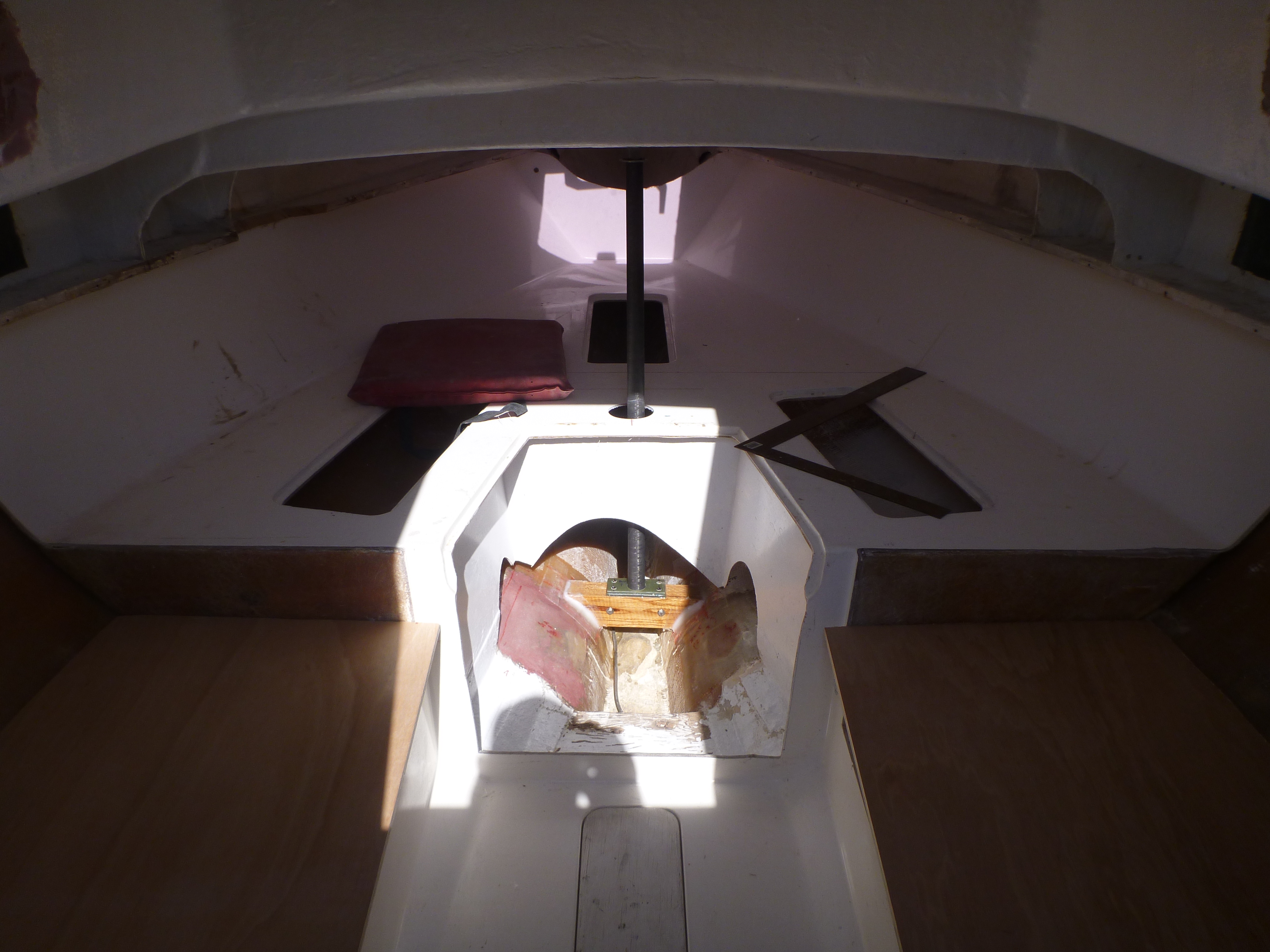
In terms of “surgery” to the boat, the project requires you to cut a hole in the v-berth platform just forward of the head (for the strut to go through, to the keel) and glass in a bottom support bearing surface just above the keel. You can optionally glass in the top support bearing surface or leave it is a removable component.
Before we discuss the top and bottom supports, let’s first discuss the strut, because that will dictate somewhat, the design and fabrication of the supports.
Strut:
Just as a humorous aside (true story!) I have a friend in Connecticut that races with some guys that have a “beater” raceboat that they use for Wednesday night beer can racing. I don’t remember what boat it is but that’s not important. They were experiencing issues with rig tuning and discovered that the deck beams were failing and causing deflection. Their fix? Remember, it was a “beater” so someone ran up to the nearest Home Depot and bought a screw type lolly column. They hacksawed it down to size, stuck it down below under the mast, and cranked it up!
Anyway, back to our project. The strut can be any sort of tubular section material as long as it has good side to side stiffness for a short length. The strut will be approx. 3 feet long. Any old piece of mast or boom section will work. Aluminum round or square tube of at least 1/8” section thickness will work. Windsurfer masts are excellent. Indeed, because I have been windsurfing since the 80’s I have tons of old gear. I used a section of a carbon fiber windsurfer mast that I broke some years ago. Scour your boatyard or local consignment shop; as mentioned you don’t need a huge piece so this should be easier than you think.
As I mentioned, get a decent sized section at least 3 feet long. Don’t cut it yet. We’ll discuss length shortly; which will be dictated by the top and bottom bearing surfaces, the adjuster, and the available clearance.
Top Support Bearing:
The top support bearing has three functions:
- Spans the underside of the deck under the mast
- Accepts and spreads the load without flexing
- Accepts the adjuster
On my boat, the underside of the deck, under the mast step and in between the two deck support beams, had a “bumped out” section (I believe some sort of additional fore/aft stiffener glassed in place) that I had to accommodate. I cut two pieces of oak stock (bolted together) with a notch to bridge this section. For stiffness, I bolted a 2x2x12 piece of 3/16” thick aluminum angle iron to the oak. I then screwed two pieces of G10 to this. I cut a hole in one of the G10 pieces to accept the top of the adjuster so as to capture it and keep it from sliding or spinning out of the top support.
The most important part of this assembly is the angle iron. If you can’t source this locally, go to onlinemetals.com where you can order a short section (they will precut a 1 foot section for you). You should be able to fabricate the rest of it with scrap material you have in your home workshop.
The general dimensions of this assembly, are based on my using the windsurfer mast section and the adjuster bolt (which I describe next), which was about 1 ½” OD at the top. If had used something larger, I would have had to make this wider.
I chose not to attach this top support bearing to the underside of the deck. It actually makes it easier to remove the whole assembly.
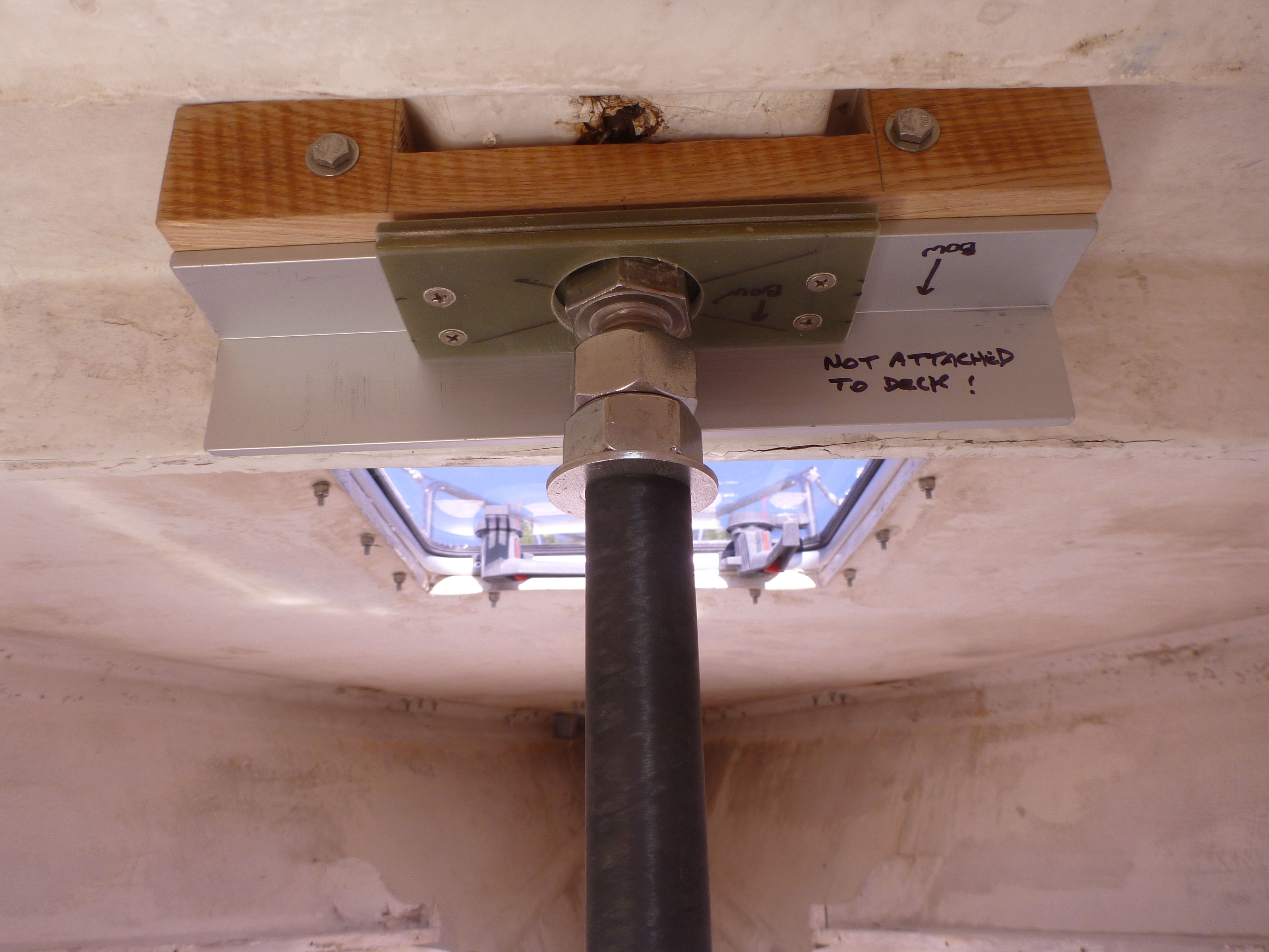
Adjuster:
See the previous photo and note how simple this is. It was a bit pricey, but I bought a 1×4 ½” SS hex head bolt, with a big fender washer and two nuts. The head of the bolt recesses into the hole in the first layer of G10, which captures it and keeps it from spinning away, and keeps the strut from tilting away from vertical. I just spin the bottom nut down with a wrench, to expand the compression strut assembly, and then tighten the top nut against it to lock it. That’s it.
You can use any sort of large threaded rod here. In this case the 1” dia bolt fit right into the top of the windsurfer mast section. If I had a bigger strut section, I would have made an insert of G10 with an overlapping flange, and then drilled a hole for the bolt.
One last benefit of that bolt is that it has a pretty big head, which provides a nice large bearing surface.
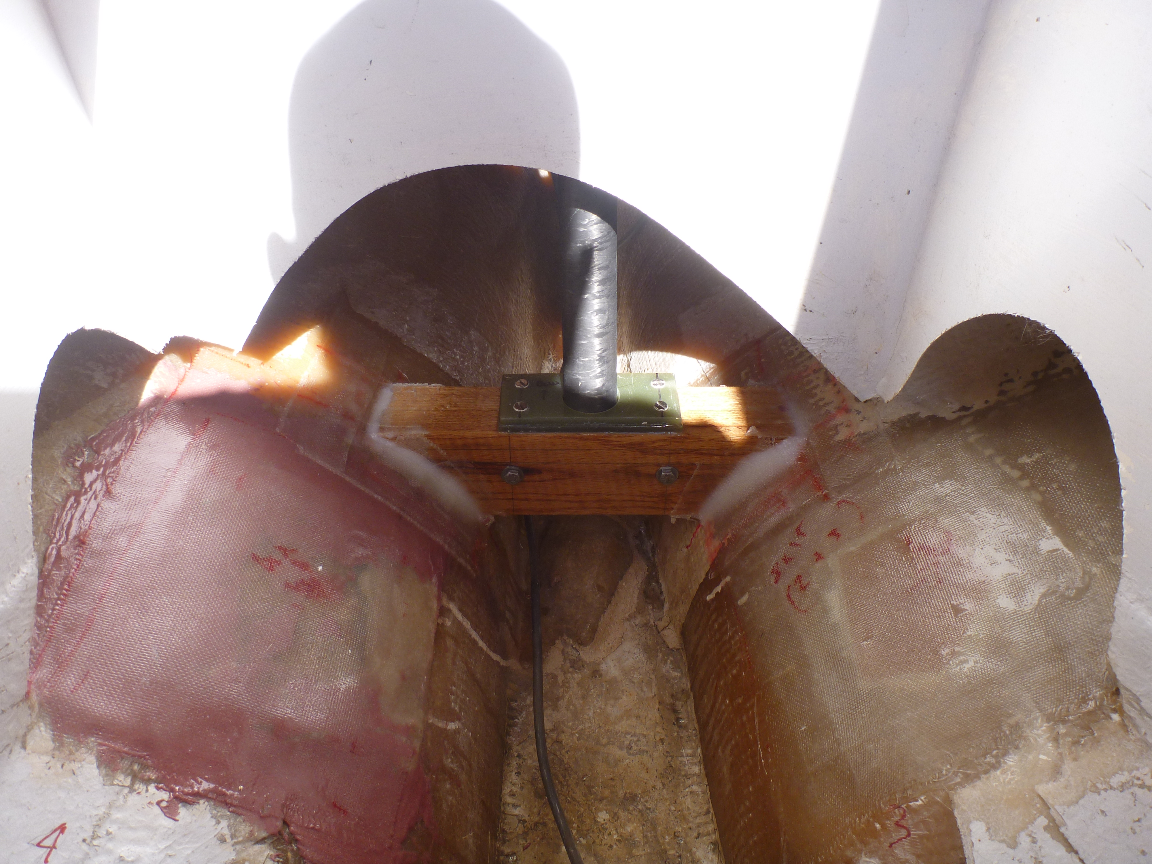
Bottom Support Bearing:
The bottom support bearing takes the compression strut load down to the keel. You don’t actually have to take this right to the keel, as you will see in the photo. Here you will fabricate and glass in a support to receive and capture the bottom end of the compression strut. I again used oak stock because I had some left from another project, and it is very strong. I epoxied and through bolted two pieces of stock that were approx. 2×6” and then shaped them to fit down into the bilge area. I elected to elevate this piece because the hull here will carry any run off water that comes in from the anchor locker. I wanted any of that water to be able to get to the bilge, rather than remain captive at this point in the hull. I probably also could have fabricated some small G10 discs to glass right down onto the keel, that would still allow water to pass.
I also cut two more pieces of G10, with one receiving a hole (via hole saw) to receive and capture the bottom of the strut.
I dropped a plumb bob from the overhead, to mark the position for glassing this to the hull. I mixed a batch of thickened epoxy to glue the bottom support in place. I then filleted it and laid strips of glass cloth to further strengthen and set this into the bilge.
As you can see in the photo, access here is not exactly easy. In tandem with this project, I was also cutting out several old thru hulls from the old head, that were completely frozen/corroded. The head compartment “floor” was a rotten piece of plywood that I cut out. I also cut away sections of the “head compartment” side walls to provide easier access for the hull repairs, and later repaired the side walls with new screw in panels.
Otherwise, you will need to work via the v berth storage access cutout panels, to get to this area. Or, even if you are not removing through hulls, you might decide to cut away a section for access, and then screw in a replacement panel.
Final Assembly:
Measure the vertical clearance between the top of the bottom support bearing, and the bottom of the top support bearing (holding the top support bearing up against the underside of the deck). Next get your adjuster, and spin the nuts up to the top, just below the head. Measure from the top of the head of the adjuster, to the bottom of the bottom nut, plus the washer. There should be about 2.5+ inches of bolt remaining exposed. So add maybe ½” to ¾” extra “clearance” to this adjuster measurement. Subtract that from the previous overall measurement between the two supports, and you have the length that you will cut the strut.
Insert the adjuster into the top of the strut. Slide the strut through the v berth access hole that you cut earlier and seat the bottom into the bottom support bearing. Now you have to tilt the strut into place with the top support bearing, under the deck. This may take some wiggling etc. which is why you added that little extra clearance to the cut measurement.
Once in place, spin the bottom nut down to snug up the compression post. For this first installation I will assume (and recommend) that you’re still “on the beach” pre-launch without the mast yet stepped. Start snugging that nut until the compression post is good and tight. There should be no movement of the assembly; you should be able to really yank on it. Short of hearing any “cracking” as you crank it up, that is about the point you want to be. Snug the locking nut down, and using two wrenches, lock the nuts together.
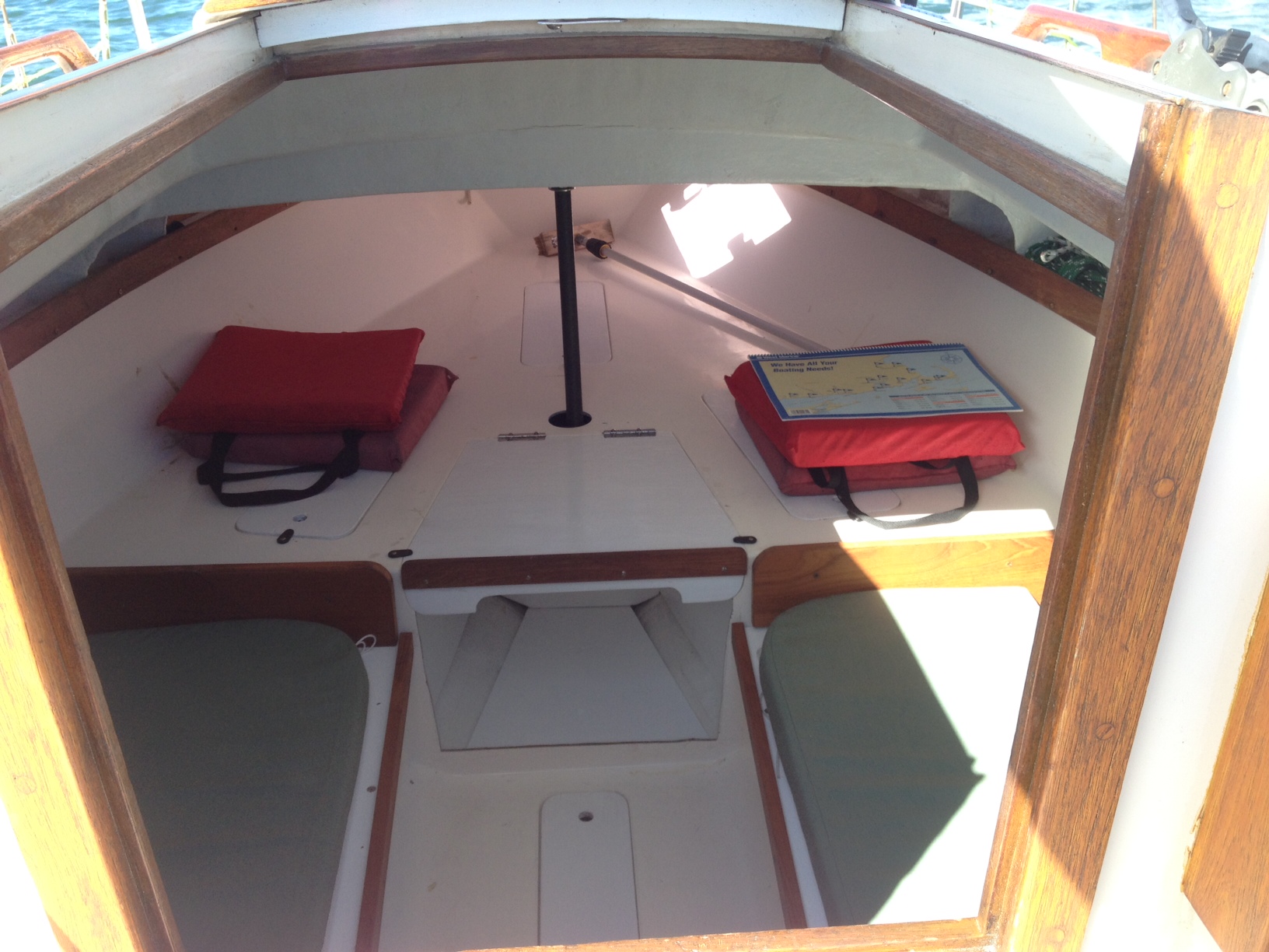
Step the mast and tune the rig. There should be a noticeable difference when tuning, and especially when sailing. My boat felt unbelievably solid after this upgrade.
If you plan to remove the strut while the boat is rigged and in the water, I recommend that you devise a means of measuring how much you expanded the adjuster, so that you can get back to that point easily. Removing the strut will surely introduce some nominal deck sag (maybe an 1/8”) and you want to be able to return to the expanded state. Perhaps cut a small measurement block or stick that exactly matches the expanded measurement of the adjuster. You can hold this up next to the adjuster when tightening, and you will know exactly how far to go. To date, although I made it removable, I have not yet found a need to remove the compression strut.
The last photo shows what the completed project looks like. (No it’s not an optical illusion, I somehow slipped off center when I hole-sawed the access hole in the v berth platform, the strut is not off center! We’re all human….)
Happy rig tuning after this one!
Postscript:
Do you want to make a fixed compression strut? The process will be similar. However, you’ll eliminate the adjuster. You’ll still need a top and bottom bearing surface.
You will need to use blocking and devise the means to jack up the deck very slightly with a hydraulic jack, essentially preloading it very slightly. (Note that you can’t depend on the V berth platform for jacking, because that mold is pretty flexible and not stiff enough for this task) While I was joking earlier about the loblolly column, that may be the best approach for this task.
Cut an exact fit strut. Glass in the bottom bearing, the strut, and the top bearing. Once the epoxy work is complete, you can release the jack pressure.
Hi Dejan,
I’m preparing to install a mast compression post similar to your design.
Although I won’t be starting work until next month I’m preparing to order the components.
Some questions:
You had noted that you “… bought a 1×4 ½” SS hex head bolt, with a big fender washer and two nuts…” Where did you find it?
Do you think that I epoxying some G 10 down onto the keel to support the bottom of the strut would provide as secure of a support ?
I’m worrying that I would not be able to fashion a secure base using the boards as you had done.
Ken